Jet JWL-1236 Wood Lathe Tips & Tricks
The Jet JWL-1236 is my first lathe so if you are new (or maybe not so new) to woodturning, this is a page to watch. As I learn to operate the lathe and explore various forms of woodturning, there are sure to be discoveries and revelations along the way. I will document them as they occur and update this page, so come back often!
Belt Replacement
The drive belt on the JWL-1236 lasts a long time under normal use, but eventually will need to be replaced. See the special story at the following link to see how to do it without surprises! - Read It!
Lathe Height
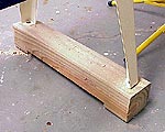 |
Raising my Jet lathe made it much more comfortable to work at.
Click image to enlarge |
I found the spindle height of the JWL-1236 to be just a little low for me and my damaged back. Extended turning session induced backaches.
I cut two pieces of 4X4 pressure treated material to act as risers which fit under the leg sets at either end of the lathe. The wood extends outside the legs about one inch front and back. I removed about 3/8-inch of material from the center of the bottom surface, leaving what amounts to 4X4 feet on either end of the riser. This helps the lathe remain stable if there is a high spot in the floor.
I secured the legs to the riser blocks with 2-inch-long lag screws and washers through the holes in each leg foot.
The result was dramatic. The lathe seems to be at the perfect height for me now, letting me turn much longer than before with virtually no back fatigue.
Mystery Indexing Pins
 |
 |
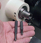
(Top) This pair of pins are identified, but their use not described in the instruction manual.
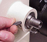
(Bottom) I use the threaded pin exclusively as it seems to provide maximum protection to the spindle shaft bearings during the installation and removal of the spur center, chucks and faceplates.
Click images to enlarge |
Included in the parts bag that came with my lathe were two important looking machined pins. The instruction manual identifies them as index pins, used for installing and removing the spur center and faceplate. Unfortunately, nothing else is said about them, particularly how they should be used.
I called Jet's Tool Doctor and found they were not sure why there were two, and why one was threaded. They were sure the pins are indeed to be used when installing or removing the faceplate.
After inspecting both pins, and the spindle boss through which they access the spindle shaft, I came to my own conclusions.
One pin has a threaded shaft with a machined taper on the end that is slightly larger than the smooth pin. When this pin is screwed through the spindle boss and into any of twelve recesses in the spindle, it locks the spindle shaft, preventing both rotating and lateral movement. This is important when installing or removing the spur center to prevent exerting side loads on the ball bearings that support the spindle shaft. This type bearing is usually designed to withstand huge radial loads, but can be damaged by even moderate lateral shocks. Installing or removing the drive spur with the spindle shaft unsupported could generate these loads, especially during spur removal. Tapping on the drift pin to remove the spur center could cause chipping of the hardened bearings, which is likely to bring about their early, if not immediate demise.
The Jet's spindle shaft bearings are probably capable of withstanding expected lateral loads, but taking this precautionary step requires a scant few seconds to accomplish but could save considerable downtime and repair money. Considering the investment in the machine, this is a simple way to help protect it.
The other pin is machined smooth and fits less precisely in the spindle boss and spindle. This pin seems useful only for preventing the spindle shaft from turning when installing and removing the faceplate or a chuck, both of which thread onto the spindle shaft. Because of this less-than-snug fit, I use the threaded pin for these operations also. Again, it takes a few seconds longer to install, but substantially reduces the chances of distorting the hole in the spindle shaft or raising a burr that could introduce metal debris into the bearings.
The screw-in pin can also be used to index the spindle in any of the twelve equally-spaced holes in the spindle shaft. This comes in handy if you want to mark segments or build a jig to do things like route flutes down the length of a turning.
In my shop, the smooth pin is resting quietly, and unused, in the drawer with the rest of my lathe-related supplies.
Drive Spur Removal
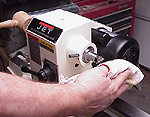 |
Getting rough when removing the drive spur from it's taper is a good way to wreck your lathe. Light taps with a mallet should pop it loose.
I catch the spur center in a rag as it has many sharp edges.
Click image to enlarge |
The manual says to insert the drift pin and "push" the drive spur out of its taper. If you have used tools with Morse tapers before, you know simple pushing seldom works. Usually a LIGHT tap or two with a mallet is necessary.
It is very important to remember that light taps are all that will be needed to free the drive spur from its taper. Hammering on the drift pin, with the spindle supported or not, is a sure way to damage the lathe.
When removing the drive spur, I hold a folded rag in my hand to catch the spur. The teeth and center point are very sharp but catching the spur is much better than letting it fall to the floor where it could be damaged.
I turned a light mallet from oak and use it to tap on the drift pin when removing the drive spur. I also turned a larger mallet, used to seat the drive spur in the work piece. Set one end of the work piece on the floor or other solid surface and seat the spur in the other end. Never hammer the wood onto the spur in the lathe. Using the tailstock ram to force the wood onto the drive spur is also a good way to damage the spindle bearings.
The same tools are used to remove the center pin from the tailstock live center and the same cautions on force apply. The tailstock does not have holes for the index pin so I use the shaft lock when removing the center with the drift pin.
Tailstock Spur Removal
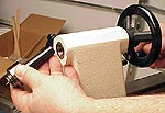 |
Removing the tailstock live center requires no tools.
Click image to enlarge |
I have received several emails from Jet JWL-1236 owners asking how to get the tailstock center out.
It also is on a #2 Morse taper, but the knock-out rod only removes the center pin, leaving the rest of the live center in place.
To remove the tailstock center, loosen the locking handle for the center itself (not the tailstock lock) and turn the handle to retract the center fully. When you feel resistance, turn it a little more and the tailstock center pops free. No other tools are necessary. |