
This is a Veteran Owned site
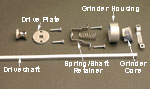
Installing A Peppermill MechanismIncluding how to shorten the driveshaftText & Photos by Tom Hintz Note: This article describes how I install peppermill mechanisms. While most mechanisms are very similar, I may not have installed the brand you have. If the instructions accompanying your mechanism differ, follow them to insure proper operation. Peppermill mechanisms are very simple machines. A long driveshaft is secured to the head of the peppermill so when turned, it rotates the grinding cutter within the grinder housing at the bottom of the peppermill. Check the Mechanism
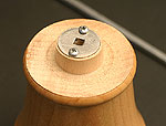
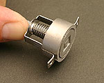
Lay out the peppermill mechanism to be sure all of the parts are present and that they fit together as designed. Though rare, finding a problem with the hardware now is much easier to deal with than after it has been installed. Be sure to screw the adjuster knob onto the shaft fully as the threads can be a little rough. Usually, if the knob feels tight when screwing it onto the driveshaft, running it on and off a few times cleans up the threads and smooths operation. Be sure to use a wire brush to clean shavings from the threads as you do this to prevent future problems. Start at the Bottom
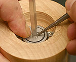
Temporarily assemble the grinder housing and spring/shaft retainer making sure the retainer seats into the grooves in the outside of the grinder housing. Also, the grinder housing is oriented with the rounded inner edge facing downward. Install the Drive PlateFit the driveshaft through the square hole in the drive plate and through the ¼"-diameter hole in the peppermill head and slide the drive plate against the tenon on the bottom of the head. Center the drive plate
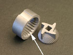
and shaft on the tenon and drill pilot holes for the screws that secure it. Install the screws and then check to be sure that the drive shaft passes through the drive plate and head without excessive resistance. Some instructions call for drilling a ¼"-diameter hole through the head for the driveshaft which can be a snug fit. Since the driveshaft does not turn within the head, as long as you can get it in and out, all is well. Remove the head from the driveshaft and set aside. Assemble the MechanismSlide the grinder core down the drive shaft, grinding teeth facing up. Place the grinder housing over the drive shaft, with the rounded end of the internal teeth facing downwards and fit it over the grinder core. Slip the spring over the drive shaft, with the narrow end against the grinder core. Note: The spring will work either way but the wide end fits over the flange on the underside of the spring/shaft retainer. Next comes the spring/shaft retainer. Slide it down the drive shaft, making sure its sides fit into the grooves in the grinder housing body.
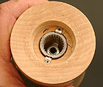
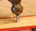
Place this assembly into the peppermill body from the bottom. Center the screw tabs of the spring/drive shaft retainer over the holes drilled earlier. Place the mechanism retainer over the assembly with the stepped side facing down and the mounting tabs also centered over the screw holes. Install the retaining screws and snug them down. These screws need not be overly tight but rather just snug enough to fully seat the two sets of mounting tabs to the peppermill body. Shortening the Drive Shaft Reducing the length of the drive shaft to fit an already-made peppermill is simple and requires few tools to accomplish. All of the drive shafts I have seen are made from aluminum, a rather soft, malleable metal that we can form in our shops. A good vice with wooden jaws, hacksaw, metal file and a ball peen hammer are all you need.
Remove the adjuster knob from the drive shaft and then the grinding mechanism from the peppermill body. Slide the parts off the driveshaft and set aside. Clamp the driveshaft in the vise and cut the excess material off at the mark. Clamp the remaining driveshaft into the vise, the cut end up, with the end about ½" above the wooden jaws of the vise. Clamp the driveshaft tightly so it can resist moderate pounding action to come next. Using the rounded face of the ball peen hammer pound the cut end of the driveshaft, expanding the metal into a mushroom shape. The blows need not be hard but rather just forceful enough to begin distorting the metal. Continue shaping the new end until it appears similar to the factory-prepared end cut off earlier. When satisfied with the newly formed driveshaft end, turn the hammer around and give the driveshaft a few blows with the flat face to smooth the surface a bit. Remove the drive shaft from the vise and slip the grinder core down to the end to check the fit. Usually there is a square recess in the bottom of the grinder core into which the mushroomed end of the driveshaft fits. It may be necessary to file the outer edges of the mushroomed end slightly to fit this recess. If desired, the hammered end of the driveshaft can be lightly sanded to smooth its surface further, though this is not necessary. Make sure all metal filings have been cleaned from the mechanism parts and peppermill before continuing!
That's it. Your peppermill is ready for use. Also see Turning A Peppermill |
||||||||||||||
Do you have a comment about this page? - Email Me! |

All written, photographic and drawn materials are property of and copyright by NewWoodworker.com LLC 2000-2019. Materials may not be used in any way without the written permission of the owner.